Intelligent headband flexi rigid PCB
December 5th, 2017
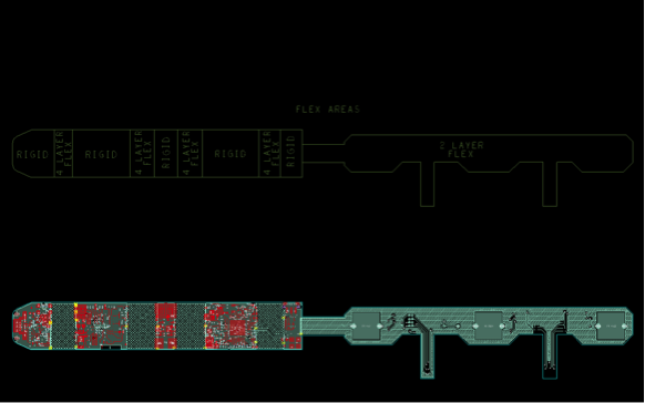
Our client required a Flexi-Rigid PCB with two separate thicknesses of flexi. Some components to be mounted on one portion of flexi.
Challenges
- We were unable to use solid copper planes in flexi portions as this would limit flexibility - how to maintain trace impedance through flexi sections and also ensure adequate power delivery
- CAD tool challenges due to components being placed on different copper layers
- Ensuring that no vias or trace direction changes occur too close to flexi/rigid board edge for design robustness reasons
Solution
- Close working with board fabricators in China allowed us to define a suitable stack-up and ensure suitable bend radius of flexible portions
- Define the flexi layer as using embedded components to allow component placement on an effective internal layer
Outcome and Technologies
- 8 layer rigid board with2 and 4 layer flexible portions
- Complex sequential build allowing microvias on different layers in different areas of the board
- Crosshatch planes in flexi portions to deliver power and allow tight enough bend radius
- Crosshatch areas have no significant impact on controlled impedance values